Bearing Engineering Tool
Deep Groove Ball Bearing Limiting Tilting Angle Calculator
Estimate the limiting tilting angle of a deep groove ball bearing from ball diameter, pitch diameter, radial clearance, and groove curvature factors.
About This Calculator
This tool helps screen alignment risk in deep groove ball bearing shaft supports. Use it as a preliminary geometry reference when reviewing bearing selection, shaft and housing design, and assembly condition risk.
Input Parameters
Enter ball diameter, bearing pitch diameter, radial clearance, inner groove curvature, and outer groove curvature. Use consistent millimeter units for dimensional inputs.
Engineering Note
The result is an engineering estimate. Final bearing selection must still consider load, speed, shaft deflection, housing accuracy, mounting fit, lubrication, temperature, and operating conditions.
Use this deep groove ball bearing tilting angle calculator when a shaft is supported by two deep groove ball bearings and you need to estimate how much housing bore position error can be tolerated before the bearings are forced into excessive angular misalignment.
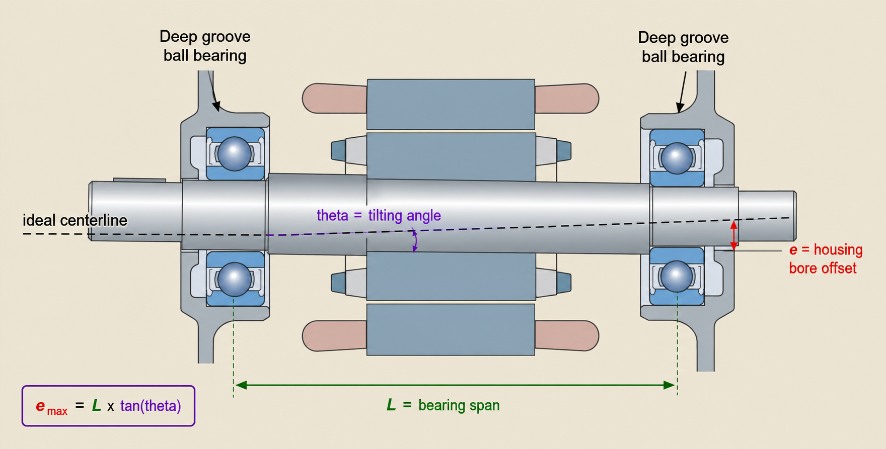
The practical problem is simple: one shaft has a bearing at each end, and each bearing is installed in a separate housing bore or bearing cavity. If the two housing bores are not on the same centerline, the shaft is forced to run at a small angle. That angular error can tilt the inner and outer rings relative to each other. Deep groove ball bearings can tolerate only limited angular misalignment, so even a small housing offset can increase noise, friction, heat, edge loading, and service-life risk.
For related selection paths, start with CXE Bearing deep groove ball bearings when the design can keep the two bearing seats accurately aligned. Review GCR15 deep groove ball bearings for common chrome-steel motor and machinery shafts, or compare self-aligning ball bearings when the housing layout cannot reliably hold a shared centerline.
What This Calculator Is Really Checking
This calculator estimates the limiting tilting angle of a deep groove ball bearing from bearing geometry. It uses ball diameter, pitch diameter, radial clearance, and groove curvature factors to estimate the maximum angular relationship that the bearing geometry may allow before the internal contact condition becomes unfavorable.
For designers and maintenance engineers, the most useful result is not only the angle itself. The practical question is how that angle relates to housing alignment:
Allowable position offset = bearing span x tan(limiting tilting angle)
If the two bearing centers are separated by distance L, and the calculated limiting tilting angle is theta, then the approximate allowable centerline offset is:
e_max = L x tan(theta)
For very small angles, a useful approximation is:
e_max approximately equals L x theta
In that approximation, theta must be in radians, not degrees.
Why This Matters in a Two-Bearing Shaft
A two-bearing shaft can look correct by part number but still fail if the bearing cavities are not aligned. Deep groove ball bearings are widely used because they are compact, low-friction, and suitable for many motor, pump, fan, roller, and light machinery shafts. They are not self-aligning bearings.
When the two bearing seats are offset, the shaft centerline no longer matches the housing centerline. The bearing rings then work with a tilt angle. If that angle stays very small, the bearing may still run acceptably depending on load, clearance, lubrication, speed, and internal design. If the angle is too large, the bearing can show symptoms that look like a lubrication or quality problem even though the root cause is geometry.
| What the calculator helps evaluate | Why it matters |
|---|---|
| Limiting tilting angle | Shows the angular misalignment boundary from bearing geometry. |
| Allowable bore offset | Converts an angle into a practical machining or assembly position error. |
| Two-bearing shaft alignment | Helps check whether the bearing cavities force the shaft into tilt. |
| Risk before production | Finds housing alignment risk before repeated noise, heat, or early failure. |
| Supplier communication | Gives the bearing supplier dimensions and angle data instead of only saying the bearing runs hot. |
Inputs That Matter for Tilt and Offset
The calculator uses five bearing-geometry inputs. For this page, the important distinction from a general clearance check is the extra dm input: pitch diameter is needed because the result is about ring tilt, not only axial free play.
| Input | Meaning | Why it affects the result |
|---|---|---|
Ball diameter D | Diameter of the rolling element. | Larger or smaller balls change the internal contact geometry. |
Pitch diameter dm | Approximate diameter of the ball center path around the bearing. | Affects the relationship between bearing geometry and tilt. |
Radial clearance Pd | Internal radial free movement before installation and load. | Clearance influences how much angular displacement can occur before contact becomes limiting. |
Inner groove curvature fi | Curvature factor of the inner raceway groove relative to the ball. | Groove conformity changes contact position and stress behavior. |
Outer groove curvature fo | Curvature factor of the outer raceway groove relative to the ball. | The outer groove geometry also affects the allowable tilt relationship. |
Ball Diameter D
Ball diameter is the rolling element diameter in the deep groove ball bearing. Use the actual ball diameter from bearing design data when available. If the ball diameter is estimated incorrectly, the tilting angle result may look precise but carry the wrong engineering meaning.
Pitch Diameter dm
Pitch diameter is the diameter of the circular path followed by the ball centers. It is not the bearing bore diameter and not the outside diameter. In a simple preliminary review, pitch diameter may be estimated from bearing geometry, but for final engineering review it should come from bearing design data or supplier confirmation.
Radial Clearance Pd
Radial clearance affects how much internal angular movement is available before the bearing geometry becomes limiting. Enter the clearance as a millimeter value. If the drawing only lists a class such as CN or C3, first confirm the numerical clearance range for that bearing size. For the separate question of how radial clearance relates to axial free play and contact angle, use the bearing clearance calculator instead of repeating that clearance workflow here.
Inner and Outer Groove Curvature fi and fo
The groove curvature factors describe how closely the raceway grooves conform to the ball. They are not catalog clearance classes and should not be guessed from the bearing suffix alone.
For many ball bearing geometry estimates, the inner groove curvature factor is often around 0.515 to 0.525, while the outer groove curvature factor is often around 0.525 to 0.535. Treat those only as preliminary review ranges. When the result will affect an end-shield bore tolerance, fixture approval, or customer complaint decision, confirm the actual geometry first.
How to Use the Calculator
Use the calculator in two stages: first estimate the bearing’s limiting tilting angle, then convert that angle into a housing bore offset for your shaft layout.
- Enter ball diameter
D. - Enter pitch diameter
dm. - Enter radial clearance
Pd. - Enter inner groove curvature factor
fi. - Enter outer groove curvature factor
fo. - Calculate the limiting tilting angle.
- Measure or define the bearing span
Lbetween the two bearing center planes. - Convert the angle into allowable position offset with
e_max = L x tan(theta).
Which Angle Should You Use for an Offset Check?
Use the calculator result as a screening value, then compare it with the actual shaft support layout. If the tool returns multiple angle values, the conservative approach is to base the bore-offset check on the smaller relevant value or apply an engineering safety margin.
The total limiting tilting angle is the main value for understanding the maximum relative angular relationship from the bearing geometry. The inner and outer ring values help explain how the geometry is distributed. The approximate value by the simplified equation is useful as a comparison check, but it should not override bearing-specific design data.
Turning Tilting Angle into Housing Bore Offset
The tilt result becomes actionable only after it is converted into a bore-center offset. That offset can be checked against the housing drawing, the actual end-shield bore measurement, or the fixture datum used during machining.
Assume:
L= distance between the two bearing center planes.theta_limit= allowable tilting angle from the calculator.e_max= approximate maximum centerline offset between the two bearing cavities.
Then:
e_max = L x tan(theta_limit)
If theta_limit is very small, the approximation is:
e_max approximately equals L x theta_limit_rad
Do not use degrees directly in the small-angle approximation. Convert degrees to radians first:
theta_rad = theta_deg x pi / 180
Example: Why Bearing Span Changes the Allowed Offset
If the limiting angle is the same, a longer bearing span allows a larger linear offset than a shorter bearing span. That does not mean the bearing is more tolerant. It means the same angular error produces a different linear measurement depending on distance.
| Bearing center distance | Same angular limit | What happens to allowable offset |
|---|---|---|
| Short shaft span | Same angle | Smaller allowable position offset. |
| Long shaft span | Same angle | Larger allowable position offset. |
This is why the calculator result should be tied to the shaft drawing. The angle is a geometry limit; the offset is the value that can be compared with CMM data, end-shield inspection records, machining setup sheets, or assembly fixture checks.
What Excessive Tilting Does to a Deep Groove Ball Bearing
Excessive angular misalignment changes the internal load distribution. Instead of smooth contact around the intended raceway path, the bearing can see concentrated stress, higher friction, and uneven ball-to-raceway contact.
Common symptoms include:
- Higher running noise.
- Higher vibration.
- Temperature rise soon after startup.
- Rough rotation after assembly.
- Unstable axial feel.
- Short grease life.
- Raceway marks shifted toward one side.
- Premature fatigue or cage stress in severe cases.
These symptoms are not proof that the bearing is poor quality. They may point to housing bore offset, shaft bending, cocked installation, shoulder error, uneven press fit, thermal distortion, or an over-constrained two-bearing arrangement.
When This Calculator Is Useful
Use this calculator when the bearing arrangement is sensitive to alignment and the shaft uses deep groove ball bearings at both ends.
| Use case | Why the calculator helps |
|---|---|
| Motor end-shield alignment review | Checks whether two bearing pockets may force the rotor shaft into angular error. |
| Pump or fan shaft support | Helps evaluate whether housing bore offset may create heat, noise, or rough rotation. |
| Small gearbox or roller shaft | Converts small angular limits into linear bore offset values for inspection. |
| Prototype troubleshooting | Helps decide whether the problem is bearing geometry, housing machining, or assembly. |
| Supplier discussion | Provides a structured way to share D, dm, Pd, fi, fo, span, and offset data. |
What This Calculator Is Not
This calculator does not approve a misaligned housing. It flags when the two bearing pockets, shaft span, and measured bore offset should be reviewed before the machine is released or rebuilt.
It Is Not a Self-Aligning Bearing Selection Tool
Deep groove ball bearings can compensate for only limited static angular misalignment. If the machine cannot keep the shaft and housing aligned, review self-aligning ball bearings, spherical roller bearings, or a different bearing arrangement.
It Does Not Include Load and Life Calculation
The tool does not calculate dynamic equivalent load, static safety factor, fatigue life, grease life, or contact stress under load. A bearing may pass the tilt geometry check and still fail if the support spacing, overhung load, belt pull, impeller load, lubrication, speed, or operating temperature is not suitable.
It Does Not Include Shaft Deflection
The calculator does not model shaft bending under load. A shaft may be aligned at rest but bend during operation. Belt tension, gear reaction, impeller load, pulley overhang, rotor weight, and thermal growth can all change the operating angle.
It Does Not Include Mounting Fit or Housing Distortion
Press fits, housing wall thickness, bore roundness, shoulder squareness, fastener tightening sequence, and thermal expansion can all change the final bearing alignment after assembly. The calculated value should be checked against actual mounted conditions.
Practical Workflow for Housing Bore Review
Use the calculator as part of a housing and shaft alignment review, not as an isolated number.
- Confirm the bearing type is a deep groove ball bearing.
- Collect
D,dm,Pd,fi, andfo. - Calculate the limiting tilting angle.
- Measure the distance between bearing center planes.
- Convert the angle into allowable bore offset.
- Compare that value with housing machining data or assembly inspection.
- Compare horizontal and vertical bore-offset measurements separately if inspection data is available.
- Check load, speed, fit, lubrication, temperature, and noise requirements.
- If the offset is too high, correct the housing alignment or review another bearing arrangement.
This process is especially useful before tooling release, CNC process approval, end-shield inspection, or prototype troubleshooting. It helps catch a hidden geometry problem before it becomes a repeated bearing complaint.
Common Mistakes to Avoid
- Treating the calculated angle as a guaranteed operating limit.
- Forgetting to convert the angle into linear offset.
- Using degrees in a radians formula.
- Checking only one bearing in a two-bearing shaft.
- Using this calculator to justify poor machining instead of correcting alignment.
- Applying this deep groove ball bearing calculator to self-aligning, spherical, tapered, or plain bearing arrangements.
Information to Prepare for a Tilt or Bore-Offset Review
Send these details when asking CXE Bearing to review a deep groove ball bearing alignment problem:
- Bearing number and size.
- Bearing type and series.
- Ball diameter
D. - Pitch diameter
dm. - Radial clearance
Pdor clearance class and bore-size range. - Groove curvature factors
fiandfo, if available. - Distance between the two bearing center planes.
- Measured housing bore offset in vertical and horizontal directions.
- Shaft fit, housing fit, shoulder squareness, and mounting method.
- Radial load, axial load, speed, temperature, lubrication, and duty cycle.
- Noise, heat, vibration, or short-life symptoms.
- Photos or inspection reports if the issue comes from a prototype or failure case.
These details make the review specific to the shaft support geometry. Without the bearing span and measured bore offset, the calculated angle is only a standalone bearing-geometry value.
FAQ
What is a deep groove ball bearing tilting angle calculator used for?
It is used to estimate the limiting tilting angle of a deep groove ball bearing from internal geometry. In a two-bearing shaft, that angle can be converted into an approximate allowable housing bore offset.
How do I convert tilting angle into position offset?
Use e_max = L x tan(theta), where L is the distance between the two bearing center planes and theta is the limiting tilting angle. For small-angle approximation, use e_max approximately equals L x theta, with theta in radians.
Does this calculator mean deep groove ball bearings can handle misalignment?
Only to a limited extent. Deep groove ball bearings are not self-aligning bearings. The calculator helps estimate a geometry limit, but the final acceptable misalignment depends on load, speed, clearance, lubrication, temperature, and bearing design.
What happens if the bearing cavity offset is too large?
The bearing may run with higher noise, heat, friction, vibration, uneven raceway contact, reduced grease life, and shorter operating life. Correct the housing alignment or review a more suitable bearing arrangement.
Can I use this calculator for self-aligning ball bearings?
No. This calculator is intended for deep groove ball bearing geometry. Self-aligning ball bearings have different internal geometry and should be reviewed with the correct catalog data.
Should I use the bearing clearance calculator instead?
Use the bearing clearance calculator when the main question is radial clearance, axial free play, or contact angle from clearance. Use this tilting angle calculator when the main question is whether two bearing seats force a deep groove ball bearing into angular misalignment.