
A deep groove ball bearing cannot be judged by bore, outside diameter, and width alone. A reliable inspection must control the material and heat treatment, ring raceway geometry, ball accuracy, cage geometry, internal clearance, vibration, rotational behavior, closures, lubricant, cleanliness, marking, and packaging. GB/T 24608-2023 provides the lot-inspection and acceptance framework, while the product drawings and related standards provide the actual limits. This guide uses production drawings for a 6208-2Z bearing to show customers what each parameter means, how it is measured, and what still needs to be specified before the bearing can be approved.
The Four Layers of Bearing Quality
Quality inspection should follow the way a bearing is made. Inspecting only the assembled bearing can detect some problems, but it cannot fully prove the condition of the steel, heat treatment, raceway profile, or concealed cage geometry.
| Quality layer | What is controlled | Why the customer should care |
|---|---|---|
| Material and heat treatment | Steel grade, hardness, microstructure, carbide condition, retained austenite when required | Determines load-carrying material condition, wear resistance, and dimensional stability |
| Component geometry | Ring dimensions, raceways, balls, cage pockets, shield grooves, chamfers, roughness, roundness, and runout | Determines fit, load distribution, friction, vibration, and assembly clearance |
| Assembly performance | Internal clearance, rotation, vibration, torque, cage movement, shield condition, grease, and cleanliness | Shows whether individually acceptable parts work correctly as one bearing |
| Lot acceptance | Lot definition, random sampling, AQL, acceptance number, rejection number, records, and traceability | Creates a consistent shipment decision instead of a subjective visual check |
GB/T 24608-2023 mainly governs the fourth layer and identifies important characteristics in the other layers. It does not replace the component drawings or the numerical product standards.
The 6208 Drawing Set Used in This Guide
The supplied ring PDF contains two pages: an outer-ring grinding drawing and an inner-ring grinding drawing. The cage drawing defines one half of a pressed-steel cage. A matching steel-ball drawing in the same 6208 drawing set specifies nine 12.000 mm G10 balls.
These are manufacturing drawings, not a complete customer specification. They define many important component limits, but they do not state the required bearing precision class, radial-clearance class, vibration grade, grease, grease fill, residual-magnetism limit, shield drawing, or finished-bearing torque limit. Those missing items must be added to the purchase specification or approved control plan.
6208 Outer Ring: What the Drawing Controls
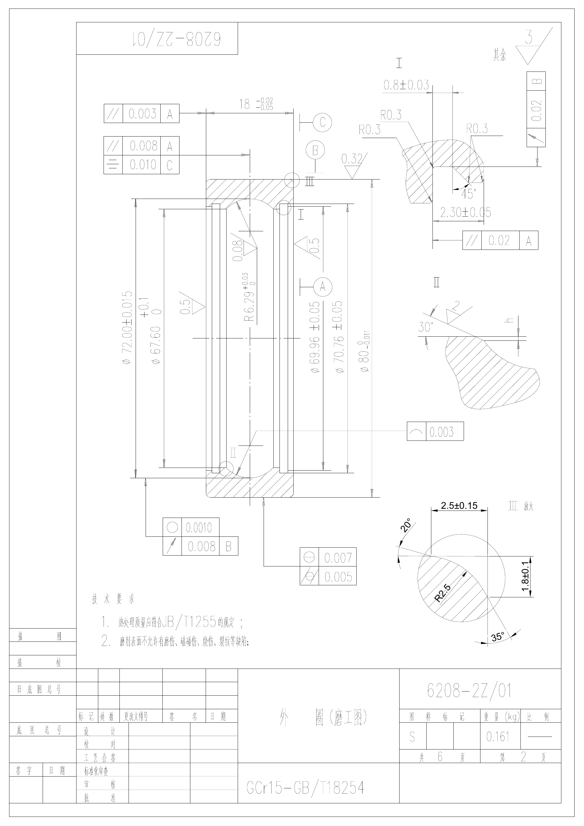
6208-2Z/01 outer-ring grinding drawing. The drawing identifies GCr15 bearing steel, ring dimensions, raceway form, shield-groove details, surface finish, datums, and geometric tolerances.
Main outer-ring requirements
| Drawing parameter | Requirement shown | What it means for bearing quality | Recommended inspection method |
|---|---|---|---|
| Material | GCr15 to GB/T 18254 | Confirms the base bearing-steel grade used for the ring | Material certificate plus spectrometric verification when required |
| Outside diameter | Ø80 with 0/-0.011 mm deviation | Controls housing fit and outer-ring location | Calibrated comparative OD gauge or air/electronic gauge; measure in multiple planes and angular positions |
| Ring width | 18 mm, limits -0.02/-0.05 mm | Controls axial mounting position and the relationship between inner- and outer-ring faces | Bench comparator or calibrated length-measuring instrument at several positions |
| Raceway groove radius | R6.29 +0.03/0 mm | Controls raceway conformity with the ball; affects contact area, stress, friction, and clearance | Contour measuring instrument or calibrated raceway-profile instrument |
| Internal land/groove diameters | Ø67.60 +0.10/0, Ø72.00 ±0.015, Ø69.96 ±0.05, Ø70.76 ±0.05 mm | Controls the internal shoulder and closure geometry around the raceway | Internal comparative gauge, air gauge, or CMM according to feature accessibility |
| Shield-groove detail | 0.80 ±0.03, 2.30 ±0.05 mm, R0.3, 45° | Controls shield retention, axial location, and non-contact running clearance | Profile projector, contour instrument, or dedicated functional gauge |
| Raceway surface roughness | Ra 0.08 µm | Reduces asperity interaction, noise, and local lubricant-film disturbance on the rolling track | Stylus profilometer using the specified cutoff and direction |
| Outside-diameter roughness | Ra 0.32 µm | Supports consistent housing fit and limits surface damage during mounting | Stylus profilometer |
| Other indicated surfaces | Ra 0.5, Ra 0.8 µm, and detail-specific values | Controls seating, closure contact, and manufacturability outside the raceway | Stylus profilometer at the marked surfaces |
| Chamfer and edge geometry | 2.5 ±0.15, 1.8 ±0.1 mm, R2.5, 20°, 35°, plus local details | Prevents shoulder interference, reduces mounting damage, and removes sharp stress-raising edges | Profile projector, radius gauge, contour instrument, or CMM |
| Geometric tolerances | Datum-referenced parallelism, symmetry, roundness, profile, and runout requirements, with limits down to the micrometer range | Controls ring seating, rotational accuracy, raceway position, and vibration | Roundness instrument, precision comparator, or CMM using the drawing datums |
The critical feature is not simply the Ø80 mm outside diameter. The raceway must be positioned correctly relative to the fitting surfaces and faces. A ring can have an acceptable OD and still produce high vibration if its raceway is out of round, wavy, incorrectly profiled, or offset from the datum system.
Why outer-ring raceway measurements matter
The groove radius establishes the geometric conformity between the 12 mm ball and the outer raceway. A smaller or larger groove radius changes the contact ellipse and contact stress. Raceway roundness and waviness influence the periodic forces generated as each ball passes through the loaded zone. Surface roughness affects running-in behavior and lubricant-film quality.
For this reason, a caliper is not an acceptable instrument for the raceway. The control plan should use a contour instrument for groove radius and profile, a roundness instrument for form and harmonic analysis where required, and a profilometer for surface roughness. Each report should identify the instrument, calibration status, measurement position, filter or cutoff where applicable, and the actual result.
6208 Inner Ring: Bore Fit Is Only the Beginning
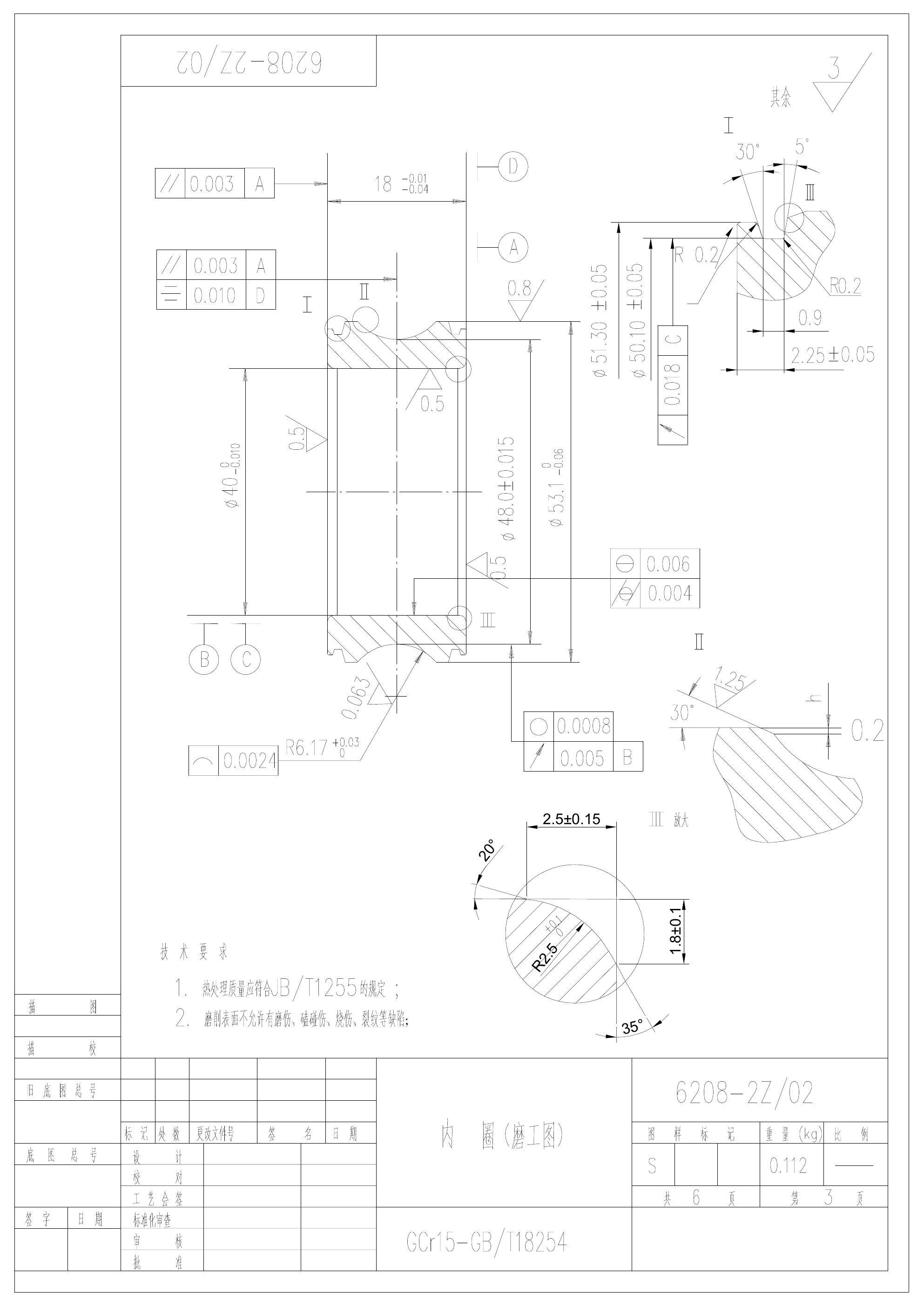
6208-2Z/02 inner-ring grinding drawing. The bore, raceway, ring width, shield land, chamfers, surface finish, and datum-related geometrical characteristics all affect the assembled bearing.
Main inner-ring requirements
| Drawing parameter | Requirement shown | What it means for bearing quality | Recommended inspection method |
|---|---|---|---|
| Material | GCr15 to GB/T 18254 | Provides the hardened rolling-contact and shaft-fitting material | Material certificate and material verification as agreed |
| Bore diameter | Ø40 with 0/-0.010 mm deviation | Controls shaft fit, mounted clearance reduction, concentricity, and resistance to ring creep | Air gauge or comparative bore gauge in multiple planes and angular positions |
| Ring width | 18 mm, limits -0.01/-0.04 mm | Controls shaft-shoulder seating and the overall axial envelope | Bench comparator at several circumferential points |
| Raceway groove radius | R6.17 +0.03/0 mm | Controls ball conformity and the inner-race contact condition | Contour measuring instrument or raceway-profile instrument |
| Raceway profile tolerance | 0.0024 mm shown on the raceway | Limits departure of the groove profile from its specified shape | Contour instrument with the drawing profile as the evaluation reference |
| Raceway surface roughness | Ra 0.063 µm | Supports smooth rolling contact, low vibration, and lubricant-film formation | Stylus profilometer |
| Bore surface roughness | Ra 0.5 µm shown | Influences mounting, fit repeatability, and the risk of fretting at the shaft interface | Stylus profilometer |
| Land and groove diameters | Ø48.0 ±0.015, Ø53.1 +0/-0.06, Ø51.30 ±0.05, Ø50.10 ±0.05 mm | Controls the inner shoulder and shield-running geometry | Comparative gauge, CMM, or optical/profile method according to the feature |
| Shield-groove detail | 2.25 ±0.05 mm, 0.9 mm, R0.2, 30°, 5°, and datum-related runout | Establishes shield clearance and helps prevent rubbing or loss of retention | Profile projector, contour instrument, and runout fixture referenced to the specified datum |
| Bore roundness | 0.0008 mm shown | Limits three-lobe or oval bore form that can distort the ring after mounting | Precision roundness instrument |
| Datum-related runout | Values including 0.005 mm relative to datum B and other drawing callouts | Controls the relationship between raceway, bore, lands, and faces | Roundness instrument or precision runout fixture using the stated datum |
| Face parallelism and symmetry | Drawing callouts include 0.003 mm parallelism and 0.010 mm symmetry relationships | Ensures square seating and correct axial position of the groove | Precision comparator or CMM using the drawing datum sequence |
| Chamfers and edge relief | 2.5 ±0.15, 1.8 ±0.1 mm, R2.5, 20°, 35°; local 30°, 1.25, and 0.2 mm details | Clears the shaft shoulder, improves mounting, and prevents sharp-edge damage | Profile projector, contour instrument, or CMM |
The inner ring is especially sensitive to installation. Even when the free ring meets the drawing, excessive shaft interference can reduce the assembled radial clearance and change raceway form. The inspection record should therefore separate unmounted component geometry from finished-bearing clearance and, when the application is critical, from mounted operating clearance.
The different ring widths are intentional inspection targets
The outer-ring drawing shows a width range of 17.95-17.98 mm, while the inner-ring drawing shows 17.96-17.99 mm. Inspectors should not reduce both requirements to “18 mm nominal.” The two rings have separate manufacturing limits, and the width relationship influences which ring face defines the assembled bearing’s axial envelope. Record inner- and outer-ring width separately before assembly.
6208 Steel Balls: Precision Must Be Measured in Micrometers
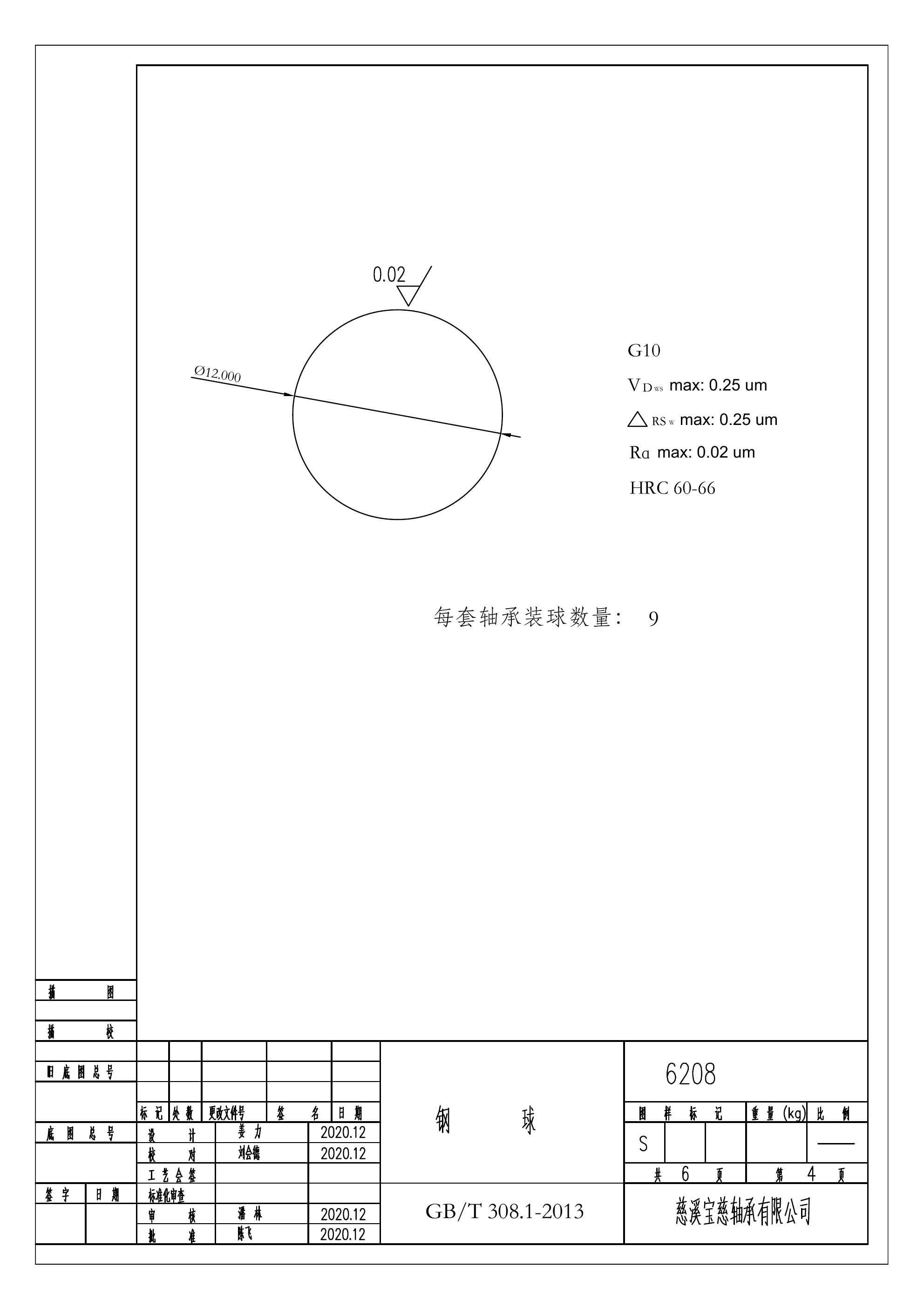
The matching ball drawing specifies nine 12.000 mm steel balls per bearing, grade G10, with form, roughness, and hardness requirements to GB/T 308.1-2013.
| Ball parameter | Drawing requirement | Meaning | Recommended inspection method |
|---|---|---|---|
| Nominal ball diameter | Ø12.000 mm | Establishes the rolling-element size used with the two raceway grooves | Ball-diameter comparator with calibrated masters |
| Ball grade | G10 | Defines a high-precision ball grade under GB/T 308.1-2013; it is not a bearing precision class | Verify the full grade report and the characteristics required by the ball standard |
| Ball diameter variation | V_Dws max 0.25 µm | Limits the difference between measured diameters of one ball | Precision ball comparator at specified orientations |
| Deviation from spherical form | ΔRsw max 0.25 µm | Limits departure from a true sphere | Roundness instrument with the correct evaluation method |
| Surface roughness | Ra max 0.02 µm | Controls the rolling-contact surface finish | High-resolution stylus or approved ball-surface roughness instrument |
| Hardness | HRC 60-66 | Verifies the hardened surface condition stated by the drawing | Rockwell hardness test on the agreed sample and prepared test condition |
| Quantity | 9 balls per bearing | Determines cage configuration, load sharing, and assembly completeness | Count during assembly; verify cage and ball-set traceability |
One oversized, undersized, or out-of-round ball can disturb load sharing around the bearing. The ball report should therefore record more than nominal diameter. It should include individual-ball variation, lot diameter variation required by the applicable ball grade, spherical-form deviation, surface condition, hardness, and traceability to the ball production lot.
6208 Pressed-Steel Cage: Geometry Controls Ball Guidance
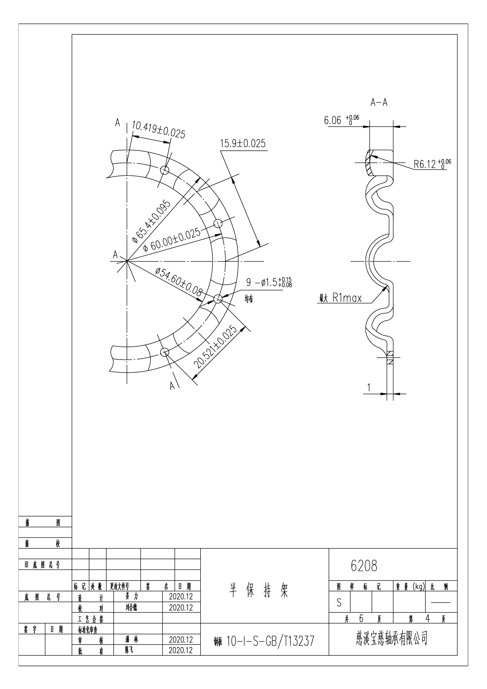
6208 half-cage drawing. Two stamped halves are assembled around nine balls. The drawing controls the formed diameters, pitch geometry, rivet holes, pocket profile, section width, sheet thickness, and edge radius.
| Cage parameter | Requirement shown | Why it matters | Recommended inspection method |
|---|---|---|---|
| Material | Grade 10 steel sheet, drawing reference 10-I-S-GB/T 13237 | Provides the strength, formability, and surface condition for stamping and riveting | Material certificate, thickness check, and material verification when required |
| Formed outer diameter | Ø65.4 ±0.095 mm | Controls clearance between the cage and surrounding ring surfaces | CMM, profile projector, or dedicated cage gauge |
| Pitch-circle diameter | Ø60.00 ±0.025 mm | Positions the ball pockets and rivet holes around the bearing pitch circle | Optical measuring machine or CMM |
| Formed inner diameter | Ø54.60 ±0.08 mm | Controls clearance from the inner-ring geometry | CMM, profile projector, or dedicated gauge |
| Circumferential feature spacing | 10.419 ±0.025, 15.9 ±0.025, 20.521 ±0.025 mm | Controls pocket and bridge distribution so every ball has comparable guidance | Optical measurement or CMM from the defined center and datum |
| Rivet holes | 9 × Ø1.5 +0.15/+0.08 mm, equally spaced | Aligns and joins both cage halves; hole error can twist or offset the cage | Go/no-go pin gauges plus optical position measurement |
| Half-cage section width | 6.06 +0.06/0 mm | Controls the combined cage width and available axial movement | Profile projector or CMM on a supported, undeformed sample |
| Pocket radius | R6.12 +0.06/0 mm | Controls how the cage guides a 12 mm ball without excessive looseness or pinch | Contour instrument, optical comparator, or calibrated profile gauge |
| Sheet thickness | 1 mm | Affects cage stiffness, rivet joint strength, mass, and pocket shape | Ball-tip or disc micrometer at locations not distorted by forming |
| Local radius | R1 max | Removes sharp transitions that can crack during forming or damage the ball | Radius gauge or optical/profile measurement |
The cage is not listed as a stand-alone “commercial part” in the scope of GB/T 24608-2023. Its acceptance limits therefore come from the cage drawing, material standard, approved sample, and the finished-bearing functional inspection.
Dimensional inspection alone is not enough. The cage should also be checked for cracks, splits, burrs, corrosion, uneven riveting, pocket deformation, loose joints, and metal contact with the rings. After assembly, rotate the bearing and inspect cage movement under controlled conditions. There should be no binding, intermittent scraping, or unstable cage behavior.
What GB/T 24608-2023 Requires Beyond the Drawings
The drawings define product characteristics. GB/T 24608-2023 defines how finished bearings and selected commercial rolling elements are inspected and how the lot decision is made.
For a standard finished bearing such as this 6208, the standard places important checks into three practical groups.
Key characteristics
For the 6208 rings and balls, the key-characteristic sampling table includes the following controls.
| Key inspection item | Standard sample for finished bearings | Lot decision |
|---|---|---|
| Inner- and outer-ring hardness and hardness difference within the same part | 2 inner rings and 2 outer rings | Ac 0 / Re 1 |
| Rolling-element hardness and hardness difference | 4 balls | Ac 0 / Re 1 |
| Inner- and outer-ring microstructure | 1 inner ring and 1 outer ring | Ac 0 / Re 1 |
| Rolling-element microstructure | 2 balls | Ac 0 / Re 1 |
| Network carbide condition | 1 of each ring; 2 balls | Ac 0 / Re 1 |
| Grinding burn on working surfaces | 1 of each ring; 2 balls | Ac 0 / Re 1 |
| Raceway roundness | 1 inner ring and 1 outer ring | Ac 0 / Re 1 |
| Rolling-element roundness | 2 balls | Ac 0 / Re 1 |
| Working-surface roughness | 1 of each ring; 2 balls | Ac 0 / Re 1 |
Retained austenite, life and reliability, sealed-bearing temperature rise, grease leakage, and dust resistance can also become key items when the customer requires them. They should be agreed before production because some tests are destructive, long-running, or require dedicated equipment.
Major and minor finished-bearing characteristics
For general finished rolling bearings outside the special product groups, GB/T 24608-2023 assigns AQL 1.5 to major items and AQL 4 to minor items. General inspection level II is used to obtain the sample size from GB/T 2828.1-2012 according to the submitted lot quantity.
The customer-facing inspection plan should include at least:
| Finished-bearing check | What must be specified or verified | Typical inspection method |
|---|---|---|
| Bore, OD, and width | Limits, variation, measurement planes, and temperature | Bearing comparator, air/electronic gauge, calibrated masters |
| Ring runout and rotational accuracy | Applicable tolerance class or drawing values | Bearing runout instrument according to the datum method |
| Radial internal clearance | Required class or numerical range; this drawing set does not state it | GB/T 25769-2010 measurement method or an agreed equivalent |
| Vibration | Acceleration or velocity method, frequency bands, and acceptance grade | GB/T 24610.2-2019 measurement setup with the agreed specification, such as GB/T 32325 or GB/T 32333 where applicable |
| Rotational flexibility | Smooth rotation without binding or abnormal intermittent resistance | Controlled hand/fixture check; instrumented torque test if a numerical limit is required |
| Starting and running torque | Numerical limit and test condition if the application is torque-sensitive | Calibrated torque instrument with defined speed, axial load, temperature, and lubricant condition |
| Shield condition | Correct installation, retention, clearance, deformation, and absence of rubbing | Visual inspection, rotation test, dimensional/functional gauge, and retention test if specified |
| Grease | Product, batch, fill quantity, distribution, and compatibility | Batch verification and controlled dispensing record; weighing or process validation as agreed |
| Cleanliness | Particle-control requirement and method | GB/T 33624 or an agreed customer method |
| Residual magnetism | Numerical acceptance limit | Calibrated residual-magnetism meter |
| Appearance | No cracks, grinding damage, corrosion, dents, burrs, contamination, or missing components | Controlled visual inspection with defect criteria and reference samples |
| Marking and packaging | Correct designation, lot traceability, preservation, label, and packaging integrity | Visual and document check |
AQL does not mean “this percentage of defects is allowed”
AQL is used to select a statistical sampling plan. It does not authorize the supplier to ship a fixed percentage of defective bearings. Once the lot size, inspection level, and AQL are known, GB/T 2828.1 provides the sample size and the applicable Ac and Re decision numbers.
An accepted sample also does not prove that every uninspected bearing is conforming. For characteristics with severe consequences, the buyer can require a tighter plan or 100% inspection. Examples may include vibration, clearance, rotational torque, appearance, or automatic dimensional sorting, depending on the application and production capability.
How the 6208 Lot Should Be Inspected
A practical control plan should combine process control with final lot acceptance.
Stage 1: Material and process verification
- Verify GCr15 material identity and material certificate for both rings.
- Verify the cage-sheet material and thickness against the cage drawing.
- Link rings, balls, cages, shields, and grease to traceable production lots.
- Record heat-treatment batch, hardness, microstructure, carbide condition, and grinding-burn inspection.
- Confirm measuring equipment calibration and master-gauge traceability.
The ring drawings still refer in their technical note to JB/T 1255. The official record for JB/T 1255-2014 lists it as withdrawn on December 12, 2023. GB/T 34891-2017 is a current national standard covering heat treatment of high-carbon chromium bearing-steel parts. Before these drawings are used as a contractual inspection basis, the supplier and customer should review the heat-treatment reference and formally agree which standard and edition govern the order.
Stage 2: Component final inspection
- Measure bore, OD, ring widths, lands, grooves, chamfers, and shield features.
- Measure raceway radius, profile, roundness, waviness where controlled, and roughness.
- Verify ball grade, diameter variation, spherical-form deviation, roughness, and hardness.
- Measure cage diameters, pitch geometry, pocket profile, rivet holes, thickness, and section width.
- Inspect all components for cracks, burns, corrosion, dents, burrs, and contamination.
Measurement data should be retained as actual values where practical. A report containing only “PASS” makes it difficult to evaluate process drift or compare later failures with the original production condition.
Stage 3: Assembly and final-bearing inspection
- Confirm nine balls, two cage halves, two shields, and the correct lubricant.
- Verify cage riveting, cage freedom, and no cage-to-ring or cage-to-ball interference.
- Measure finished radial internal clearance.
- Check rotational flexibility and any specified starting/running torque.
- Measure vibration using the agreed method and grade.
- Inspect shields for correct seating, deformation, rubbing, and retention.
- Verify grease identity and controlled fill.
- Check cleanliness, residual magnetism, marking, preservation, and packaging.
- Release or reject the lot using the agreed GB/T 24608-2023 sampling plan.
Information Still Missing from the Current Drawing Package
The drawings are strong manufacturing references, but they are not enough to approve the complete 6208-2Z bearing for shipment. The following items should be added to the customer specification or quality agreement:
- Finished-bearing precision class, such as the required dimensional and rotational tolerance class.
- Radial internal-clearance class or numerical clearance range.
- Vibration method and acceptance grade.
- Starting and running torque limits, if required.
- Complete shield drawing, material, retention requirement, and rubbing/clearance criteria.
- Grease product, fill quantity, allowable variation, and cleanliness requirement.
- Residual-magnetism limit.
- Finished-bearing appearance defect standard or approved limit samples.
- Marking, rust prevention, packaging, shelf-life, and traceability requirements.
- Required reports, sampling frequency, record-retention period, and rules for process changes.
- Whether retained austenite, life, leakage, dust, temperature-rise, or reliability testing is required.
Without these details, two suppliers can manufacture rings to the same drawings but deliver bearings with different clearance, grease, vibration, torque, cleanliness, and field behavior.
What the Customer’s Inspection Report Should Contain
A useful 6208 report should be traceable and readable without access to the factory’s internal system.
- Customer, purchase order, bearing designation, drawing revision, and quantity.
- Submitted lot size and lot identities for rings, balls, cages, shields, and grease.
- Applicable standards and approved deviations.
- Inspection level, AQL, sample size,
Ac,Re, and actual nonconforming count. - Instrument identification and calibration status.
- Actual dimensional and geometrical results for the selected samples.
- Hardness and metallographic results.
- Raceway roundness, profile, and surface-roughness results.
- Ball grade and ball-inspection results.
- Cage dimensional and appearance results.
- Finished clearance, vibration, rotational, shield, grease, cleanliness, and appearance results.
- Final acceptance decision, inspector, approver, and inspection date.
For bulk deep groove ball bearings, this report structure is more useful than a generic certificate stating only that the goods passed inspection. Buyers sourcing metric ball bearings or chrome-steel deep groove ball bearings can use the same logic while changing the drawing values and application-specific limits.
Common Inspection Mistakes
- Measuring only
40 × 80 × 18 mmand calling the bearing qualified. - Treating ring dimensions as a substitute for finished radial clearance.
- Checking raceway radius but not raceway roundness, profile, waviness, or roughness.
- Accepting G10 balls from the label without reviewing the actual ball inspection report.
- Inspecting cage dimensions before forming but not checking the assembled cage for interference or loose riveting.
- Using a hand-spin test as the only vibration or torque assessment.
- Failing to state the vibration grade, clearance class, grease, and shield requirements before production.
- Taking all samples from one carton instead of sampling randomly across the submitted lot.
- Reporting only pass/fail results without actual measurements or instrument traceability.
- Continuing to cite a withdrawn heat-treatment standard without customer approval.
Frequently Asked Questions
Does GB/T 24608-2023 contain all 6208 dimensional tolerances?
No. It defines inspection rules, characteristic classifications, sampling, and lot acceptance. The actual limits come from the component drawings, applicable product standards, and the customer specification.
Why inspect the rings before assembling the bearing?
Finished-bearing checks cannot fully reveal material condition, grinding burn, groove-radius error, raceway profile, or every geometric relationship. Component inspection prevents concealed defects from entering assembly.
Is G10 the precision class of the 6208 bearing?
No. G10 is the grade of the individual steel balls under the ball standard. The finished bearing precision class is a separate requirement and is not stated by the supplied drawing set.
Can a 6208 pass dimensional inspection and still be noisy?
Yes. Vibration can be influenced by raceway waviness, ball variation, contamination, clearance, cage behavior, shield rubbing, lubricant condition, mounting damage, or process defects. Boundary dimensions alone cannot predict noise.
Should every bearing be tested for vibration and clearance?
GB/T 24608-2023 provides a sampling framework, but a customer can require 100% testing for selected final characteristics. The decision should consider application risk, production volume, test capability, and the consequence of failure.
What is the most important missing item in these drawings?
There is no single missing item. For complete-bearing approval, the priority gaps are the finished precision class, radial-clearance requirement, vibration grade, shield specification, grease specification, and finished-bearing acceptance plan.
Quality Is the Agreement Between Drawing, Process, and Test
The 6208 drawings show that bearing quality is created at the micrometer level. The bore and OD establish fit, the raceway profile and surface finish control rolling contact, the balls control load sharing, and the cage keeps nine balls correctly separated and guided. The finished bearing must then prove that these components work together through clearance, vibration, rotation, closure, lubrication, and cleanliness checks.
GB/T 24608-2023 gives buyers and suppliers a common way to sample and accept the shipment. The drawings define what must be made; the inspection methods define how it is measured; and the purchase specification fills the performance gaps not shown on the drawings. CXE Bearing can prepare a model-specific inspection plan when the customer provides the bearing designation, drawing revision, precision and clearance classes, vibration requirement, lubricant, operating conditions, quantity, and required quality records.